This is a project to show various information from a Home Assistant installation on a nice and clear LED-based display. The protocol used is MQTT so other automation platforms could also be used. However this document assumes Home Assistant is the home automation platform in use.


(More screenshots are in the assets directory.)
This software can be targeted at RP2040, RP2350 and ESP32 based boards.
I have had it running on:
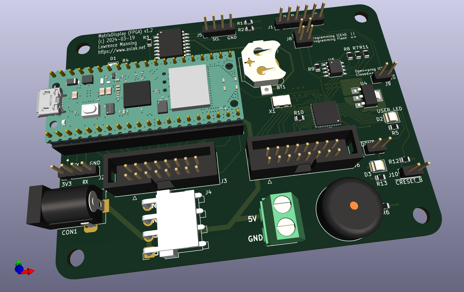
- My own board based on a Pi Pico W, with the HUB75 protocol being generated by an iCE40UP5 (PDF) FPGA. The board also sports a buzzer:
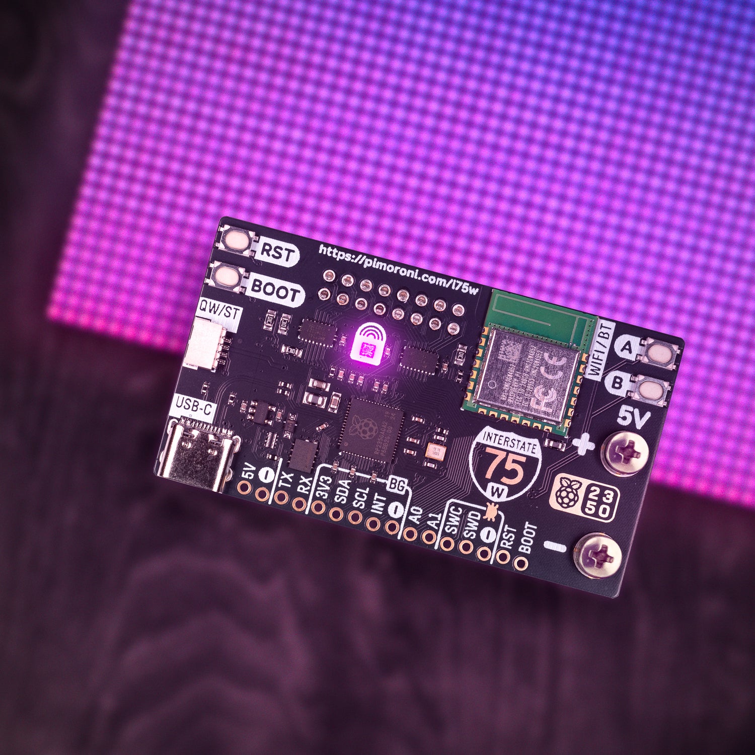
- The Pimoroni Interstate 75W which is an RP2350 based board:
- The Adafruit MatrixPortal S3 which is an ESP32-S3 based board:

To build the code for a Pico based board the Pico-SDK is required with FreeRTOS.
To build the code for an ESP32 based board only the ESP-IDF is required, since FreeRTOS is folded in.
This project does not make use of any Arduino libraries.
For all boards, an I2C bus is available which can be configured at build time to use multiple sensor ICs. See the section on sensors below for a list of supported boards. Also Pico-based boards can make use of an onboard passive buzzer, if the board has one attached to a GPIO pin.
The following information can currently be shown:
- Time and Date as obtained via SNTP; the display doubles up as a mantlepiece clock
- Inside the house temperature information
- Current weather conditions
- Weather forecast for the next few hours
- The next 3 items in your calendar
- If music is playing you can see the track title name, album name and artist name
- Transport information: two sets of two lines of text for use in showing the time of the next train, bus, etc
- Periodically, arbitrary messages can be scrolled across the bottom of the display showing things like energy usage, share prices or anything else
The system also supports notifications, which will scroll across the display. Critical and normal notifications are supported. Lastly there is support for displaying an icon when there is movement in the house porch, should such a thing be needed.
The communication link, as mentioned, to the Home Assistant install is via MQTT, with auto-discovery being supported to create a device in Home Assistant for the control and monitoring of the system.
The system runs atop of FreeRTOS. This project requires the support of SMP mode on all the boards it runs on.
The display drawing code supports the usual graphical primitives, all utilising the 64x32 screen: proportional and non proportional fonts, icons (used for showing weather state, etc), filled and unfilled boxes, filled and unfilled circles, lines, and a primitive alpha channel scheme for producing a dimmed box suitable for drawing other elements like text atop of. The display output path has a brightness control, allowing the screen's intensity to be scaled according to a brightness value.
You require a working MQTT setup in your Home Assistant, so make sure that is working before going further. Only non SSL connections are currently supported.
The data shown on the display, beside the time and date, is pushed up to the display via Home Assistant automations using MQTT. This affords a large amount of flexibility in what is shown, vs the display being configured with entities which it is interested in which is an alternative approach I discarded. Eventually I hope to have a nice HA blueprint that makes this part of the setup of the automation easier, but for now these notes will have to suffice.
A complete example of an automation for configuring most aspects of the display is included in this repo. This example is probably slightly out of date, but it should be fairly simple, for the experienced Home Assistant user, to tailor this to any particular setup. Note that it relies on other tremplates, for example the share prices rely on a template helper which uses a 3rd party component which scrapes Yahoo for price information.
The automation I have running divides the chore of sending up the needed information into four blocks: weather, media player, calendar and porch. The weather information includes the temperature data for inside the house.
Since there are a large number of sources of possible change, the trigger for the weather data publish event is a simple 5 minute timer. For the media player, the trigger is on the player device's Content-ID (which will cover when the current track rolls over to the next track, or if a new track is manually selected), or the player is turned on or off. I'm using the iCal out-of-tree integration for my calendar and the calendar trigger is thus the first three entities it creates. The porch trigger is simply the motion sensor's motion entity.
In terms of the actions needed, each trigger produces an MQTT publish of the correctly formatted JSON data. The media player block is simple enough it can be reproduced in full here:
service: mqtt.publish
data:
  qos: 0
  retain: false
  topic: matrix_display/media_player
  payload_template: |
    {% set result = {
      'state': states("media_player.squeezebox"),
      'artist': state_attr("media_player.squeezebox", "media_artist"),
      'album': state_attr("media_player.squeezebox", "media_album_name"),
      'title': state_attr("media_player.squeezebox", "media_title"),
    } %}

    {{ result | to_json }}
Refer to the complete example automation YAML to get started.
For the source of transport information I have written my own custom integration for my local bus company. Other sources are possible; previously I use a Go script, which I will continue to included here as a source of inspiration, which does MQTT publishing operations based on web-scraped data, bypassing Home Assistant.
Before creating the automation you should verify basic functionality of your display by activating auto-detection. This is done by sending a MQTT message with the text ON in it to the topic matrix_display/autodetect.
Configuration of the MQTT broker details is described in the building section, below.
Note that the topics to do with Weather, Calendar, Scroller, Transport and Porch are "global", whilst all other topics can be targeted at a particular instance of the display, should you happen to have more then one in your house. The idea is to not force the user to publish the weather topics multiple times and instead let each display feed from the a single data source. See the building section for how the MQTT topics, and entity names if you are using HA autodiscovery, can be set.
The following topics are subscribed to by the device:
JSON formatted temperature and weather information. Refer to the example automation for the schema.
JSON formatted calendar information for the next three appointments.
The current transport situation. JSON data of the form:
[
    {
        "Towards": "The moon",
        "DeparturesSummary": "1h 3h"
    },
    {
        "Towards": "Mars",
        "DeparturesSummary": "1d 30d"
    }
]
(Yes I'm aware those dictionary keys have inconsistent case. Likely because the generator of the data was a Go script.)
Currently only two destinations are supported. Strings need to be kept as short as possible, as no scrolling is done.
JSON formatted scroller message text. This is an array of upto four messages, each upto 256 characters long. The messages are shown in sequence with a configurable interval between messages.
There is provision to show up and down arrows, intended for showing stock prices and the like. To make use of this use the magic sequence -UP- or -DOWN- in the message text.
The states() of the porch motion sensor. This is not JSON formatted. That is, it needs to be either on for motion or off for no motion.
JSON formatted media player information. If the state of the player is anything other than playing or paused then this screen is skipped.
If the board is so equipped, its buzzer can play a Ring Tone Text Transfer Language tune, allowing you to reminisce about the 1990s. If you weren't alive then: RTTTL is a simple text format describing the pitch and duration of a sequence of notes. 1990s phones used these tunes as ringtones.
Why you'd want to do this I'm not quite sure, but it is pretty neat and I had fun writing the code, and testing it out with different tunes I found online.
Here is a rendition of the Mission Impossible theme:
mission_imp:d=16,o=6,b=95:32d,32d#,32d,32d#,32d,32d#,32d,32d#,32d,32d,32d#,32e,32f,32f#,32g,g,8p,g,8p,a#,p,c7,p,g,8p,g,8p,f,p,f#,p,g,8p,g,8p,a#,p,c7,p,g,8p,g,8p,f,p,f#,p,a#,g,2d,32p,a#,g,2c#,32p,a#,g,2c,a#5,8c,2p,32p,a#5,g5,2f#,32p,a#5,g5,2f,32p,a#5,g5,2e,d#,8d
A plain text message to present, wrapped in a dictionary:
{
  "critical": true,
  "text": "This is a very important notification",
  "rtttl_tune": "... tune data ..."
}
The screen is flashed white, the buzzer will play some tones, and the message will be scrolled across the screen in large lettering. If a critical message is shown, it will be shown in red text and will be shown 3 times, and the beeps are a little more "aggressive".
Note that rtttl_tune is optional. If it is missing the standard beeps, for that level of criticality, are played.
This is the "switch" part of the light, which is used to control the brightness of the panel. Set it to ON or OFF.
Note that the MQTT light uses the on_command_type mode of last meaning the brightess is set before the light is turned on with this topic. If the light is turned off and then on the previous brightness will be asserted.
Sets the intensity of the panel, from 0 to 255.
Set to on to enable grayscale mode. I added this just for the fun of doing so; it's not likely to be very useful.
This is the root of around ten configuration parameters which can be used to alter the behavior of the display. They are described below.
Activate autodiscovery by sending ON (case sensitive). The system will send a set of responses back via MQTT which will create:
- A "light" for setting the brightness of the panel
- A switch for the grayscale mode
- A number for configuring the number of snowflakes on the screen (see the configuration section)
- Sensors will also be created, assuming they are configured
A number of topics are recognised as configuration parameters. All of these appear under matrix_display/configuration/. The default value is given in parens:
clock_duration(1000) : The number of frames that the clock is shown for.clock_colon_flash(0) : The frame count with which the colons in the time hold their steady state. 20 is a good rate. 0, the default, to disable the flashing.inside_temperatures_scroll_speed(3) : The number of frames between each vertical pixel movement on the inside temperatures screen.current_weather_duration(200) : The number of frames the current weather screen is displayed for.weather_forecast_duration(500) : The number of frames the weather forecast screen is displayed for.media_player_scroll_speed(1) : The number of frames between each horizontal pixel movement for this screen.calendar_scroll_speed(3) : A vertical scroll is used on the calendar screen. This is the number of frames between movements.transport_duration(300) : The number of frames the transport information appears on screen.scroller_interval(10000) : The number of frames between the "scroller" appearing at the bottom of the screen. After the message has been scrolled across the screen the next message in the queue of up to four will be shown.scroller_speed(2) : And the speed of the scroller.snowflake_count(0) : The count of snowflakes to show.
Notes:
It's a little annoying using frame counts for lengths of time, but it is the most exact way to measure time in the animation system. For a static screen, the frame rate is just under 100 frames a second on my display. Thus the clock appears for around 10 seconds by default.
To suppress a screen, set its duration to zero.
The scroller is intended to display extra tidbits of information over the top of anything else that might be on the screen at any one time. An array of upto four messages can be passed in and are shown in sequence with a configurable delay between them. I currently use this fascility to present detailed information on the current weather conditions and for showing current prices for a few stocks, all formatted with the templating capabilities of Home Assistant.
Snowflakes are only for Christmas! At least if you are in the northern hemisphere. A simple algorithm is used to move white pixels around, and this configuration item sets the count of snowflakes. Past about 50 snowflakes the screen is hard to read, but the effect is still quite pleasant. Snowflakes make use of a special feature in the display code: snowflake pixels will appear at maximum brightness regardless of the brightness setting.
One of the first things I automated was to turn the panel off when it isn't needed. This was straightforward for me as I have a reliable presence sensor setup in my lounge, where I have my display. I simply turn the panel "light" off when the room is empty, just like the lights in the ceiling.
All of the notifications that happen in my Home Assistant setup go through an automation script. This script can, based on how it is called, generate alerts on the user phones, or it will speak the notification via the Nabu-Casa Text To Speech service, or it will put the notification on the matrix display via an MQTT publish service call. I use notifications for such things as:
- When it's going to rain (it might be fun to try to get the buzzer to play back some pitter-patter noises)
- When Home Assistant detects someone is on their way home
- Upcoming appointments in the calendar
It might be useful to control the screen brightness using the time of day or room light level, but I've not yet bothered with such details.
The build system is cmake. You should install either (or both) the ESP-IDF, Pico-SDK and FreeRTOS-PICO repositories and set everything up as per the instructions. Verify that you can build examples for the SDK you require before proceeding to build this project.
There are a number of configuration files used:
local.cmake: The main configuration file. Sets the board used, MQTT topic and device name, WiFi details and MQTT broker details,boards/*.cmake: A per board description file. You should not have to touch these files, unless you want to play with supporting another board type.sensors.cmake: A description of what I2C sensors are attached to the board.
Here is a typical local.cmake:
set(MATRIX_DISPLAY_BOARD    adafruit_matrix_portal_s3)

set(DEVICE_NAME            lounge_matrix_display)
set(DEVICE_PRETTY_NAME     "Lounge Matrix Display")

set(WIFI_SSID               wifi-ssid)
set(WIFI_PASSWORD           wifi-password)
set(SPI_TO_FPGA             1)
set(MQTT_BROKER_IP          10.0.0.1)
set(MQTT_BROKER_USERNAME    user)
set(MQTT_BROKER_PASSWORD    password)
MQTT_BROKER_PORT can be used to set the MQTT port number, should the default 1883 not be used.
The following options are mandatory:
WIFI_SSID should be set to the SSID (network name) the Wi-Fi will be connecting too. WIFI_PASSWORD should be set to the network password.
MQTT_BROKER_IP should be to the IP (v4) host running MQTT, with MQTT_BROKER_USERNAME and MQTT_BROKER_PASSWORD being set to the needed credentials for the broker.
A board description cmake file resembles the following, which is the description for the ESP32-S3 based Adafruit MatrixPortal S3:
set(MATRIX_DISPLAY_SDK          ESP32)

set(FRAME_DELAY_MS              20)

set(I2C_INTERFACE               1)
set(I2C_SDA_PIN                 16)
set(I2C_SCL_PIN                 17)

set(HUB75_RED1_PIN              42)
set(HUB75_GREEN1_PIN            41)
...
A key variable is MATRIX_DISPLAY_SDK which sets which SDK to use for building, either ESP32 or PICO. For Pico-SDK based builds PICO_BOARD sets the chip in use, either pico_w (RP2040 based) or pico2_w (RP2350 based).
For all board types FRAME_DELAY_MS sets the task delay between frames, since it seems that RP2040, RP2350 and ESP32-S3 do not all perform identically. The rest is mostly pinning information.
Note that the Pico-SDK implementation supports driving the HUB75 display either via the iCE40UP FPGA present on my board (see the appendix at the bottom of this document for an outline) or the Pico's PIO mode. This is configured via the SPI_TO_FPGA variable. If it is 0 PIO mode will be used.
For the ESP32 implementation only simple bitbanging is supported, though perhaps a little surprisingly this performs very well with no observed flickering, even with 256 levels of brightness supported.
The last set of variables of interest for boards relates to buzzers. The firmware can drive a passive buzzer, though currently only Pico (1 and 2) based boards are supported. There are two variables:
set(BUZZER_PRESENT              1)
set(BUZZER_PIN 27)The sensors.cmake describes what sensors are attached to the I2C bus:
set(BME680_PRESENT          1)
set(DS3231_PRESENT          0)
set(BH1750_PRESENT 1)If BME680_PRESENT is set to 1, a BME680 breakout board like this one should be attached to the I2C bus. Note that the SDO pin should be connected to ground, which will yield the correct slave address of 0x76. In this case the temperature, humidity and pressure sensor values will come from this board.
I2C address: 0x76.
This is a holdover from when this projected used this RTC IC to hold the time and date instead of using SNTP. Because it was trivial to do a temperature reading can still be obtained from this IC via this option.
I2C address: 0x68
This is a light-level sensor. Home Assistant calls these "illuminance" sensors. The implementation is very crude at present, but a single value between 0 and 255 can be obtained.
I2C address: 0x23
For Pico based boards you can trigger a build via the shell:
mkdir build
cd build
cmake ..
make
For the Pico based boards the resultant src/matrix-build.uf2 should then be copied to the Pi Pico either via the USB filesystem or via picotool. The script in this repo at flasher-pico.sh is crude but an effective wrapper around picotool.
For ESP-IDF builds I prefer to use the above cmake invocation instead of using idf.py, but either works. There is another script called flasher-esp32.sh which wraps esptool.py.
Debug output is produced as the system runs. It can be captured on the Pico W's USB port or the UART on GPIO0 and GPIO1. In the case of ESP32 boards you can obtain a trace via the USB port. It will include both project-specific tracing and the text from ESP-IDF itself. Note that even if there are issues connecting the Wi-Fi, you should still see, via the HUB75 panel, startup progress messages scrolling across as the system starts:
- Starting up
- Starting Wi-Fi connection
- Wi-Fi connected!
- SNTP client created
- MQTT up; awaiting time
Clearly the scope for such a display as this is fairly limitless. The following is a randomly ordered list of ideas. Some of these changes are possible without touching the firmware code.
- Display the latest sports scores.
- Display a list of the newest YouTube videos for creators the user is subscribed to.
- Somehow suppress the transport information screen when it's not needed. Unsure how this could be done though.
- Consider scrolling through more future hours on the weather forecast screen, eg. the next six 3 hours-apart forecast instead of just the next three. It might be distracting to look at though.
- Consider more configurability of the screen, for instance text colours.
- The ability to display arbitrary images or possibly small animation sequences might be cute. There's a number of ways to do this. One obstacle is it would probably require SSL support and a HTTP client.
This firmware was originally designed only to be run on a Pi Pico W attached to a main board I have designed. The idea of running this code on other boards, especially those based around the ESP32, came much later.
The board I designed and built features the following main components:
- Power via 5V barrel jack
- A Pi Pico W (obviously)
- A DS3231 (PDF) I2C Real Time Clock
- CR122 battery backup
- IDC16 HUB75 connector attached to the Pico W
- Buzzer
- iCE40UP FPGA
- N25Q32A (PDF) 32MBit SPI Flash
- IDC16 HUB75 connector attached to the FPGA
- LED
It is possible to build the firmware with support for either the attached FPGA or not, via the SPI_TO_FPGA variable as described above. If the FPGA is not used, the HUB75 display will be driven via the RP2040 PIO mode, which at the point I made the decision to investigate solutions using FPGAs had some drawbacks including very slight flickering when the RP2040 is under heavy network load.
- MDFPGA The PCB design for the base board.
- HUB75 Controller A HUB75 LED matrix controller implemented in Verilog.
- Go South Coast integration My integration for retrieving bus times for the local, to me on the south coast of England, bus company.