Arduino is an open-source electronics platform based on easy-to-use hardware and software. Arduino boards are able to read inputs - a light on a sensor, a finger on a button, or a Twitter message - and turn them into an output - activating a motor, turning on an LED or publish something online. You can tell your board what to do by send a set of instructions to the microcontroller on the board. To do so you use the Arduino programming language (based on Wiring), and the Arduino Software (IDE), based on Processing. Over the years Arduino has been the brain of thousands of projects, from everyday objects to complex scientific instruments. Arduino board designs use a variety of microprocessors and controllers. The boards are equipped with sets of digital and analog input/output (I/O) pins that may be interfaced to various expansion boards ('shields') or breadboards (for prototyping) and other circuits. The boards feature serial communications interfaces, including Universal Serial Bus (USB) on some models, which are also used for loading programs. The microcontrollers can be programmed using the C and C++ programming languages, using a standard API which is also known as the Arduino language.
Welcome! Before you start regulating and modulating the world around you, you'll need to set up the software to program your board. The Arduino Software (IDE) allows you to write programs and upload them to your board. On the Arduino Software page, you will find two options: If you have a reliable Internet connection, you should use the online IDE (Arduino Web Editor). It will allow you to save your sketches in the cloud, having them available from any device and backed up. You will always have the most up-to-date version of the IDE without the need to install updates or community-generated libraries. If you prefer to work offline, use the latest version of the desktop IDE. The Arduino Software (IDE) - contains a text editor for writing code, a message area, a text console, a toolbar with buttons for common functions and a series of menus. It connects to the Arduino hardware to upload programs and communicate with them.
Programs written using Arduino Software (IDE) are called sketches. These sketches are written in the text editor and are saved with the file extension .ino. The console displays text output by the Arduino Software (IDE), including complete error messages and other information. The bottom righthand corner of the window displays the configured board and serial port. The toolbar buttons allow you to verify and upload programs, create, open, and save sketches, and open the serial monitor. Additional commands are found within the five menus: File, Edit, Sketch, Tools, and Help. The menus are context-sensitive, which means only those items relevant to the work currently being carried out are available.
The Arduino Software (IDE) uses the concept of a sketchbook: a standard place to store your programs (or sketches). The sketches in your sketchbook can be opened from the File > Sketchbook menu or from the Open button on the toolbar. The first time you run the Arduino software, it will automatically create a directory for your sketchbook. You can view or change the location of the sketchbook location from with the Preferences dialogue. Beginning with version 1.0, files are saved with a .ino file extension. Previous versions use the .pde extension. You may still open .pde named files in version 1.0 and later, the software will automatically rename the extension to .ino.
Allows you to manage sketches with more than one file (each of which appears in its own tab). These can be normal Arduino code files (no visible extension), C files (.c extension), C++ files (.cpp), or header files (.h). Before compiling the sketch, all the normal Arduino code files of the sketch (.ino, .pde) are concatenated into a single file following the order of the tabs shown. The other file types are left as is.
Before uploading your sketch, you need to select the correct items from the Tools > Board and Tools > Port menus. The boards are described below. On the Mac, the serial port is probably something like /dev/tty.usbmodem241 (for an UNO or Mega2560 or Leonardo) or /dev/tty.usbserial-1B1 (for a Duemilanove or earlier USB board), or /dev/tty.USA19QW1b1P1.1 (for a serial board connected with a Keyspan USB-to-Serial adapter). On Windows, it's probably COM1 or COM2 (for a serial board) or COM4, COM5, COM7, or higher (for a USB board) - to find out, you look for USB serial device in the ports section of the Windows Device Manager. On Linux, it should be /dev/ttyACMx , /dev/ttyUSBx or similar. Once you've selected the correct serial port and board, press the upload button in the toolbar or select the Upload item from the Sketch menu. Current Arduino boards will reset automatically and begin the upload. With older boards (pre-Diecimila) that lack auto-reset, you'll need to press the reset button on the board just before starting the upload. On most boards, you'll see the RX and TX LEDs blink as the sketch is uploaded. The Arduino Software (IDE) will display a message when the upload is complete, or show an error. When you upload a sketch, you're using the Arduino bootloader, a small program that has been loaded onto the microcontroller on your board. It allows you to upload code without using any additional hardware. The bootloader is active for a few seconds when the board resets; then it starts whichever sketch was most recently uploaded to the microcontroller. The bootloader will blink the onboard (pin 13) LED when it starts (i.e. when the board resets).
Libraries provide extra functionality for use in sketches, e.g. working with hardware or manipulating data. To use a library in a sketch, select it from the Sketch > Import Library menu. This will insert one or more #include statements at the top of the sketch and compile the library with your sketch. Because libraries are uploaded to the board with your sketch, they increase the amount of space it takes up. If a sketch no longer needs a library, simply delete its #include statements from the top of your code.
Support for third-party hardware can be added to the hardware directory of your sketchbook directory. Platforms installed there may include board definitions (which appear in the board menu), core libraries, bootloaders, and programmer definitions. To install, create the hardware directory, then unzip the third-party platform into its own sub-directory. (Don't use "arduino" as the sub-directory name or you'll override the built-in Arduino platform.) To uninstall, simply delete its directory.
This displays the serial sent from the Arduino board over a USB or serial connector. To send data to the board, enter text and click on the "send" button or press enter. Choose the baud rate from the drop-down menu that matches the rate passed to Serial.begin in your sketch. Note that on Windows, Mac or Linux the board will reset (it will rerun your sketch) when you connect with the serial monitor. Please note that the Serial Monitor does not process control characters; if your sketch needs complete management of the serial communication with control characters, you can use an external terminal program and connect it to the COM port assigned to your Arduino board.
Arduino programming language can be divided into three main parts: functions, values (variables and constants), and structure.
Functions
digitalRead()
Reads the value from a specified digital pin, either HIGH or LOW. Syntax - digitalRead(pin) Parameters - pin: the Arduino pin number you want to read Returns - High or Low Example Code: Sets pin 13 to the same value as pin 7, declared as an input.

delay()
Pauses the program for the amount of time (in milliseconds) specified as a parameter.
Syntax : delay(ms)
Parameters : the number of milliseconds to pause. Allowed data types - unsigned long.
Returns : Nothing
Example Code:

isAlpha()
Analyse if a char is alpha (that is a letter). Returns true if thisChar contains a letter. Syntax : isAlpha(thisChar) Parameters : thisChar: variable. Allowed data types: char. Returns :true: if thisChar is alpha.

interrupts()
Re-enables interrupts (after they’ve been disabled by noInterrupts(). Interrupts allow certain important tasks to happen in the background and are enabled by default. Some functions will not work while interrupts are disabled, and incoming communication may be ignored. Interrupts can slightly disrupt the timing of code, however, and may be disabled for particularly critical sections of code. Syntax : interrupts() Parameters : None Returns :true: if thisChar is alpha.

Structure
Sketch
loop()
After creating a setup() function, which initializes and sets the initial values, the loop() function does precisely what its name suggests, and loops consecutively, allowing your program to change and respond. Use it to actively control the Arduino board.

setup()
The setup() function is called when a sketch starts. Use it to initialize variables, pin modes, start using libraries, etc. The setup() function will only run once, after each powerup or reset of the Arduino board.

Control Structure
while
A while loop will loop continuously, and infinitely, until the expression inside the parenthesis, () becomes false. Something must change the tested variable, or the while loop will never exit. This could be in your code, such as an incremented variable, or an external condition, such as testing a sensor.
Syntax :
while (condition) { // statement(s) }
Parameters: condition: a boolean expression that evaluates to true or false.

for
The for statement is used to repeat a block of statements enclosed in curly braces. An increment counter is usually used to increment and terminate the loop. The for statement is useful for any repetitive operation, and is often used in combination with arrays to operate on collections of data/pins.
Syntax :
for (initialization; condition; increment) { // statement(s); } Parameters : initialization: happens first and exactly once.
condition: each time through the loop, condition is tested; if it’s true, the statement block, and the increment is executed, then the condition is tested again. When the condition becomes false, the loop ends.
increment: executed each time through the loop when condition is true.

Arithmetic operators % (remainder)
- (addition)
- (subtraction)
- (multiplication) / (division) = (assignment operator)
Enough talks! Now let's have a working demonstration of an Arduino project.
In this project, we will “Read a potentiometer, and print its state out to the Arduino Serial Monitor.”
This example shows you how to read analog input from the physical world using a potentiometer. A potentiometer is a simple mechanical device that provides a varying amount of resistance when its shaft is turned. By passing a voltage through a potentiometer and into an analog input on your board, it is possible to measure the amount of resistance produced by a potentiometer (or pot for short) as an analog value. In this example, you will monitor the state of your potentiometer after establishing serial communication between your Arduino and your computer running the Arduino Software (IDE).
Hardware Required: Arduino Board, 10k ohm Potentiometer, Circuit
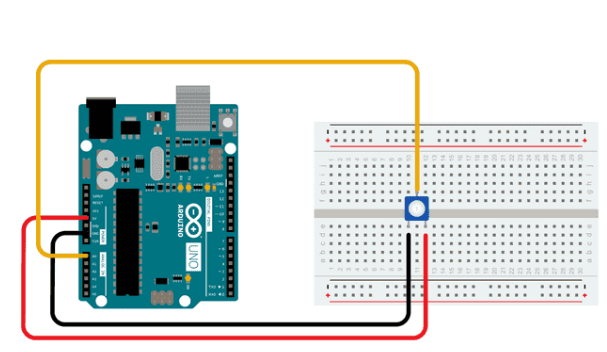
Connect the three wires from the potentiometer to your board. The first goes from one of the outer pins of the potentiometer to the ground. The second goes from the other outer pin of the potentiometer to 5 volts. The third goes from the middle pin of the potentiometer to the analog pin A0.
By turning the shaft of the potentiometer, you change the amount of resistance on either side of the wiper, which is connected to the center pin of the potentiometer. This changes the voltage at the center pin. When the resistance between the center and the side connected to 5 volts is close to zero (and the resistance on the other side is close to 10k ohm), the voltage at the center pin nears 5 volts. When the resistances are reversed, the voltage at the center pin nears 0 volts, or ground. This voltage is the analog voltage that you're reading as an input.
The Arduino boards have a circuit inside called an analog-to-digital converter or ADC that reads this changing voltage and converts it to a number between 0 and 1023. When the shaft is turned all the way in one direction, there are 0 volts going to the pin, and the input value is 0. When the shaft is turned all the way in the opposite direction, there are 5 volts going to the pin and the input value is 1023. In between, analogRead() returns a number between 0 and 1023 that is proportional to the amount of voltage being applied to the pin.

In the sketch below, the only thing that you do in the setup function is to begin serial communications, at 9600 bits of data per second, between your board and your computer with the command:
Serial.begin(9600);
Next, in the main loop of your code, you need to establish a variable to store the resistance value (which will be between 0 and 1023, perfect for an int datatype) coming in from your potentiometer:
int sensorValue = analogRead(A0);
Finally, you need to print this information to your serial monitor window. You can do this with the command Serial.println() in your last line of code: Serial.println(sensorValue);
Now, when you open your Serial Monitor in the Arduino Software (IDE) (by clicking the icon that looks like a lens, on the right, in the green top bar or using the keyboard shortcut Ctrl+Shift+M), you should see a steady stream of numbers ranging from 0-1023, correlating to the position of the pot. As you turn your potentiometer, these numbers will respond almost instantly.

You can find more basic tutorials here https://docs.arduino.cc/built-in-examples/