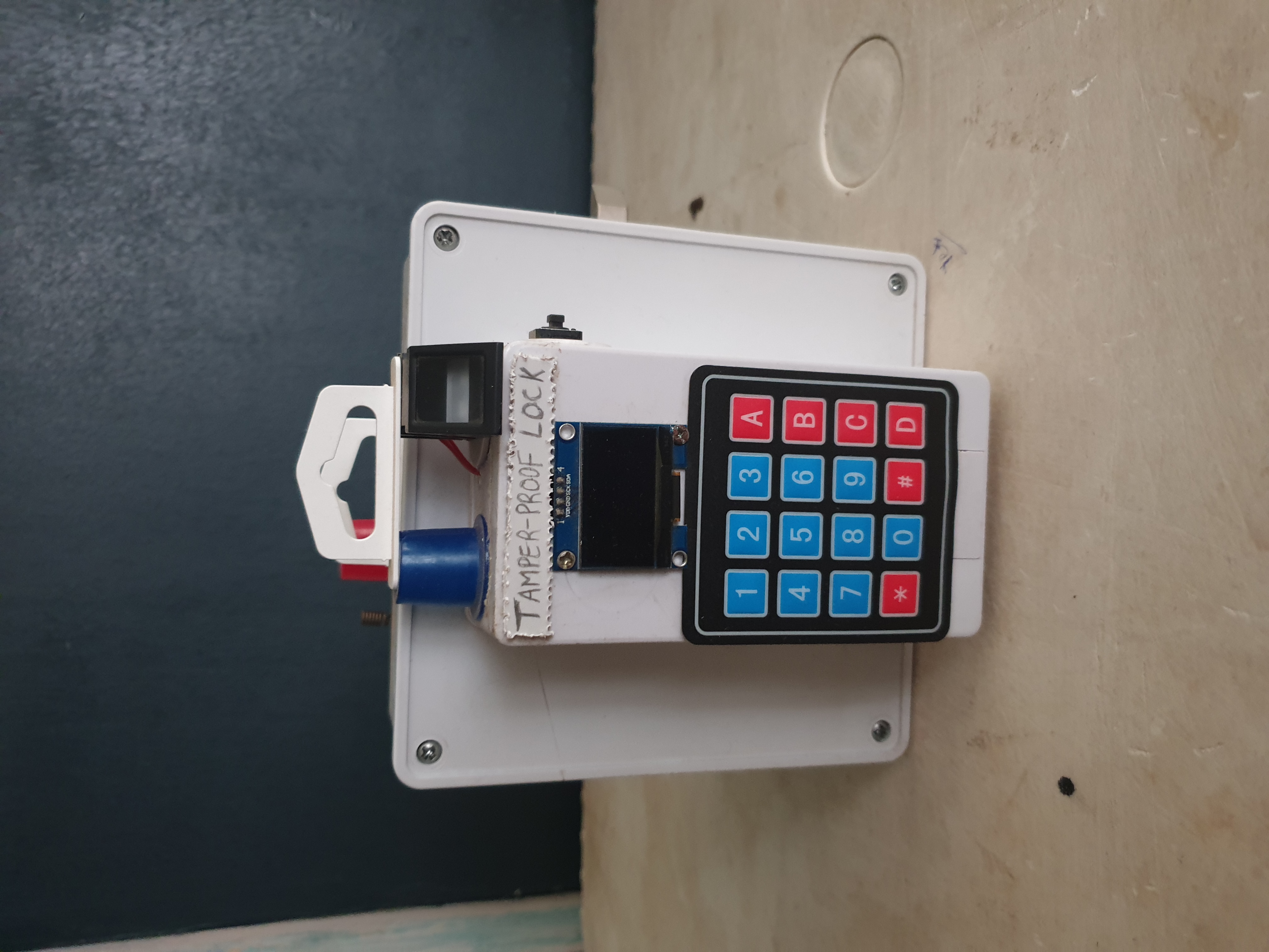
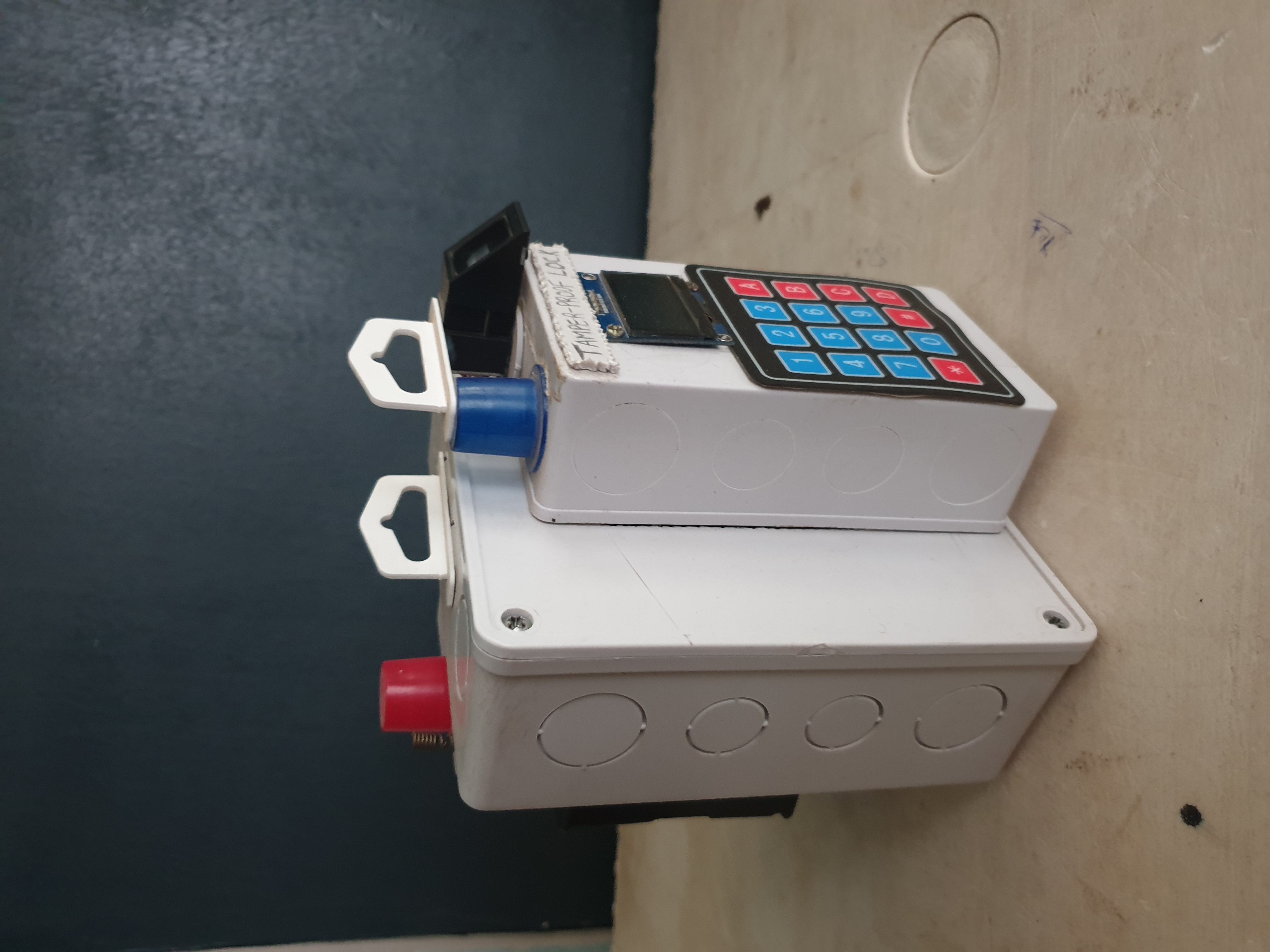
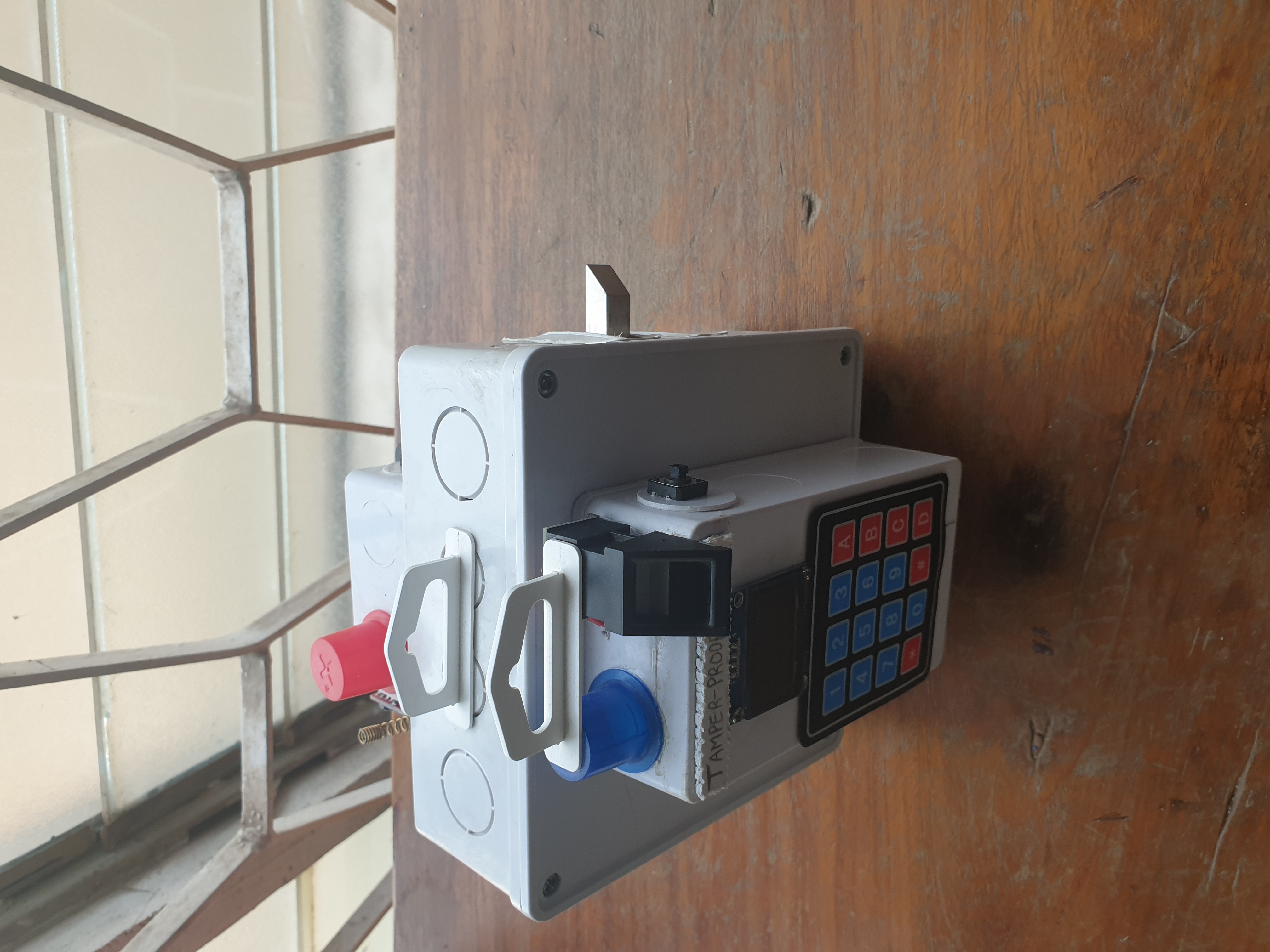
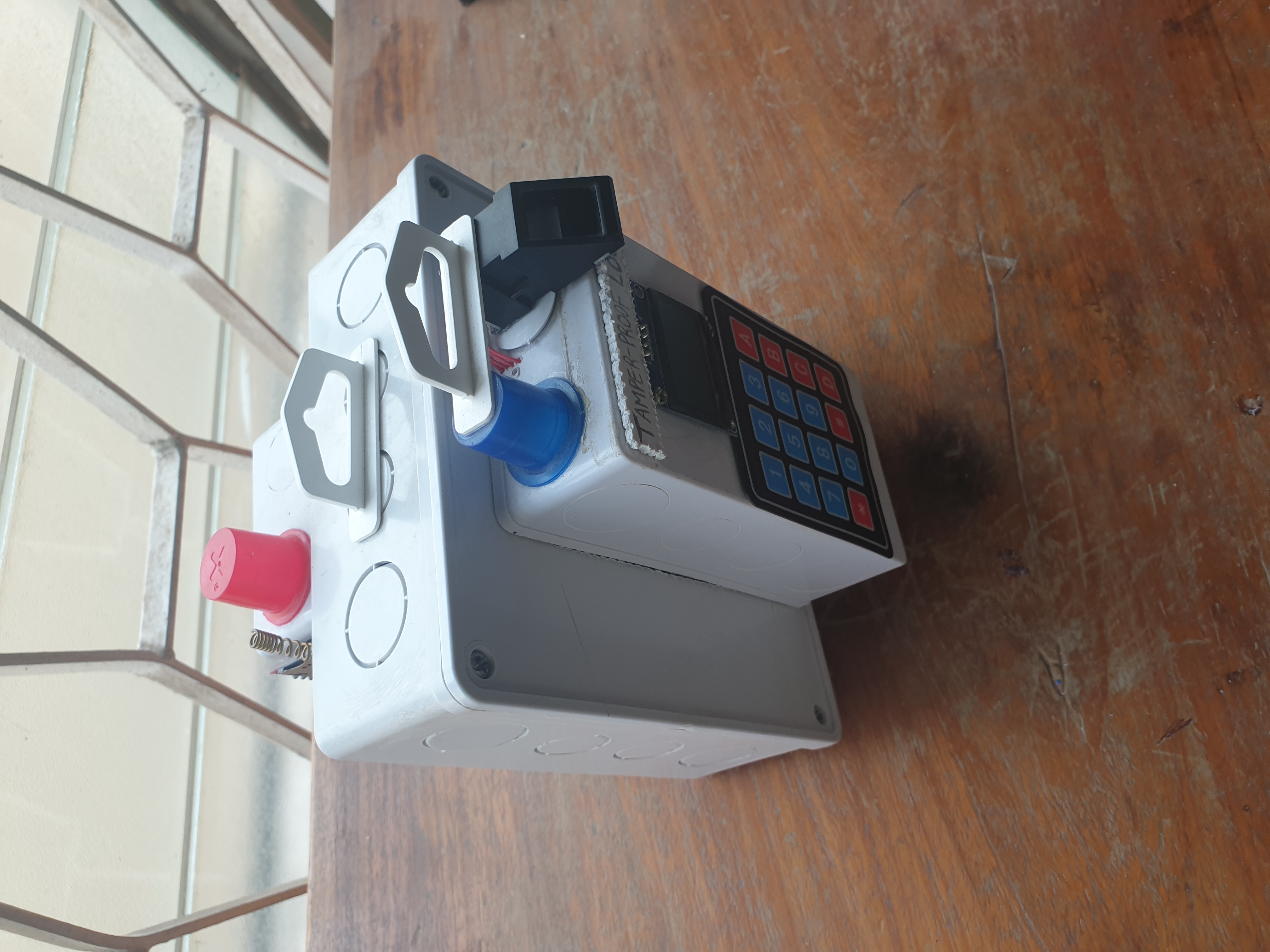
The Native Smart Lock is a functional prototype designed and developed for a school project.
It is a secure, door locking system that can be accessed using multiple options for access control,
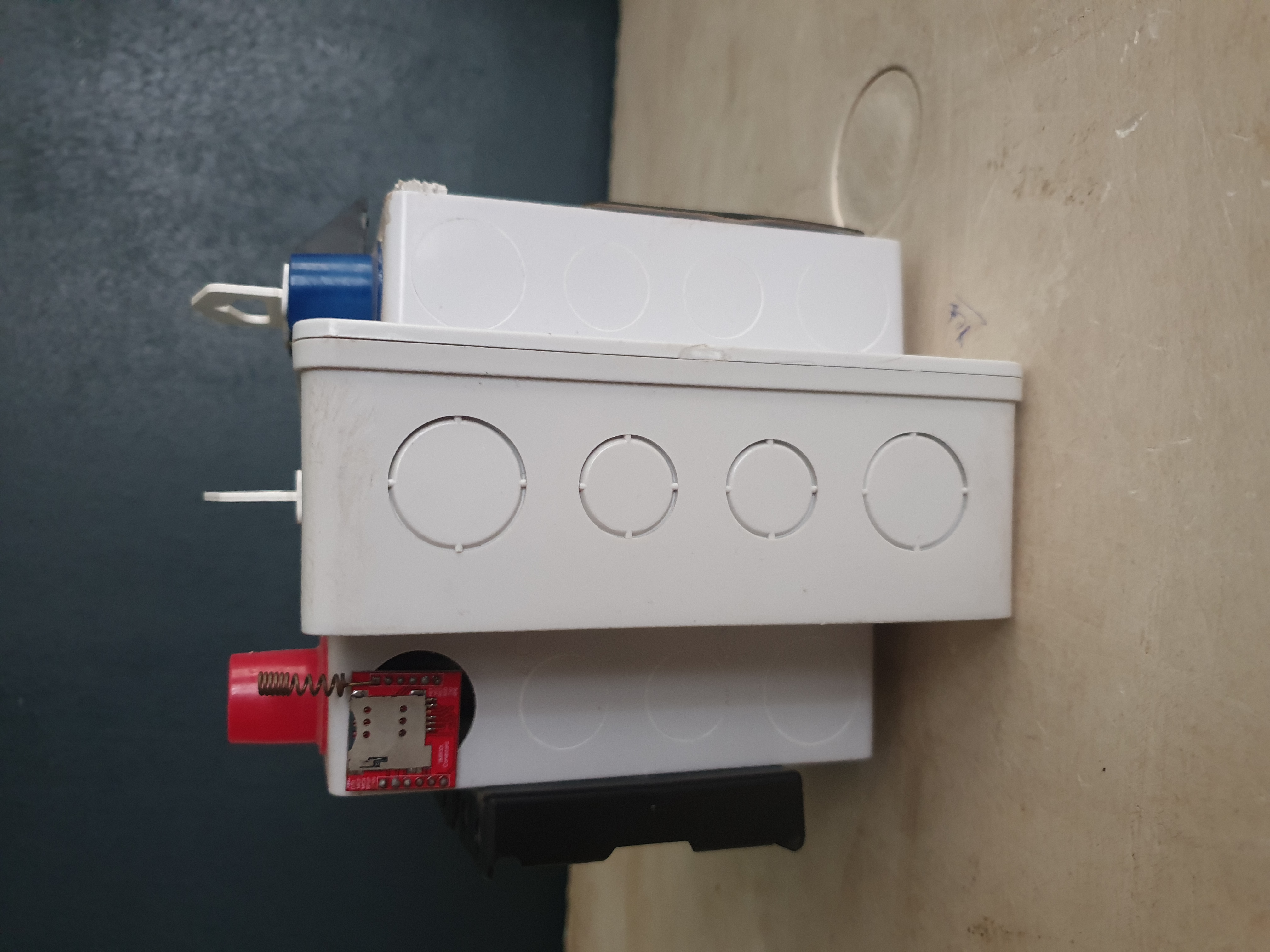
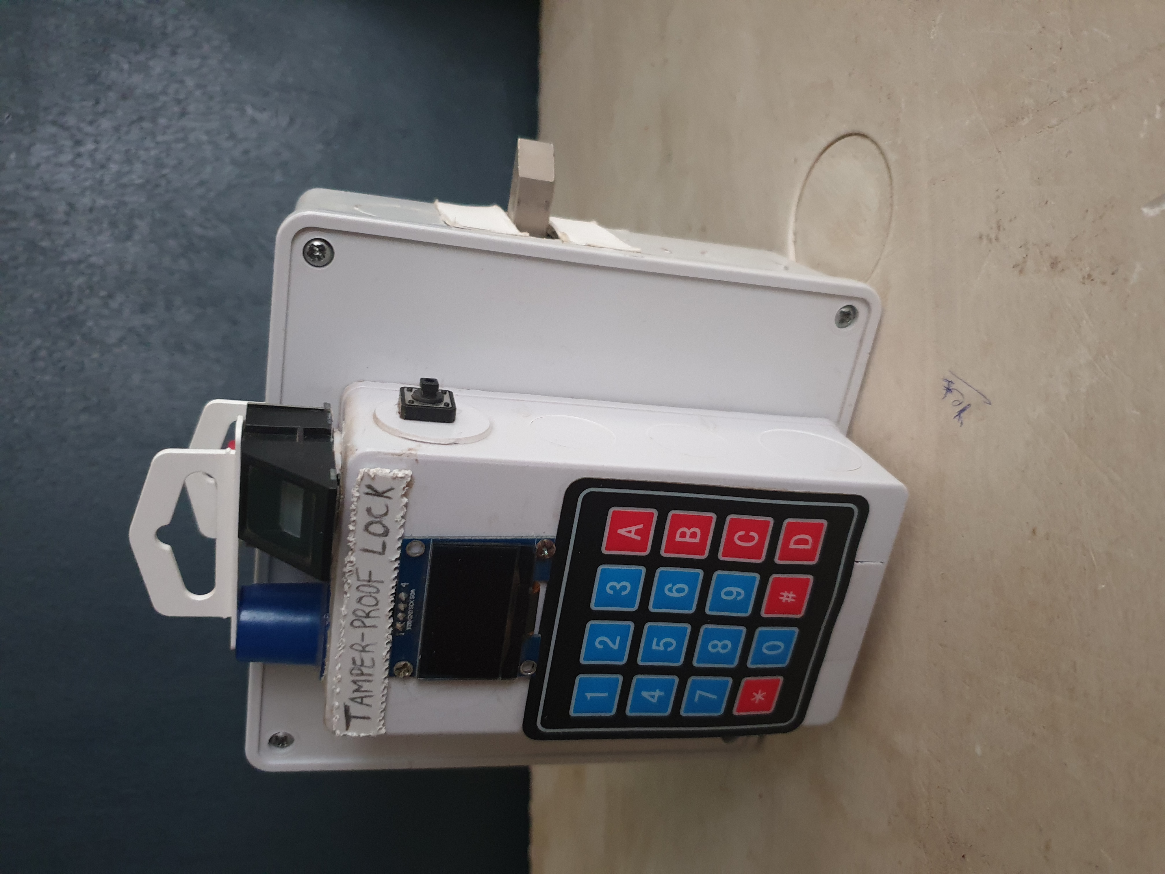
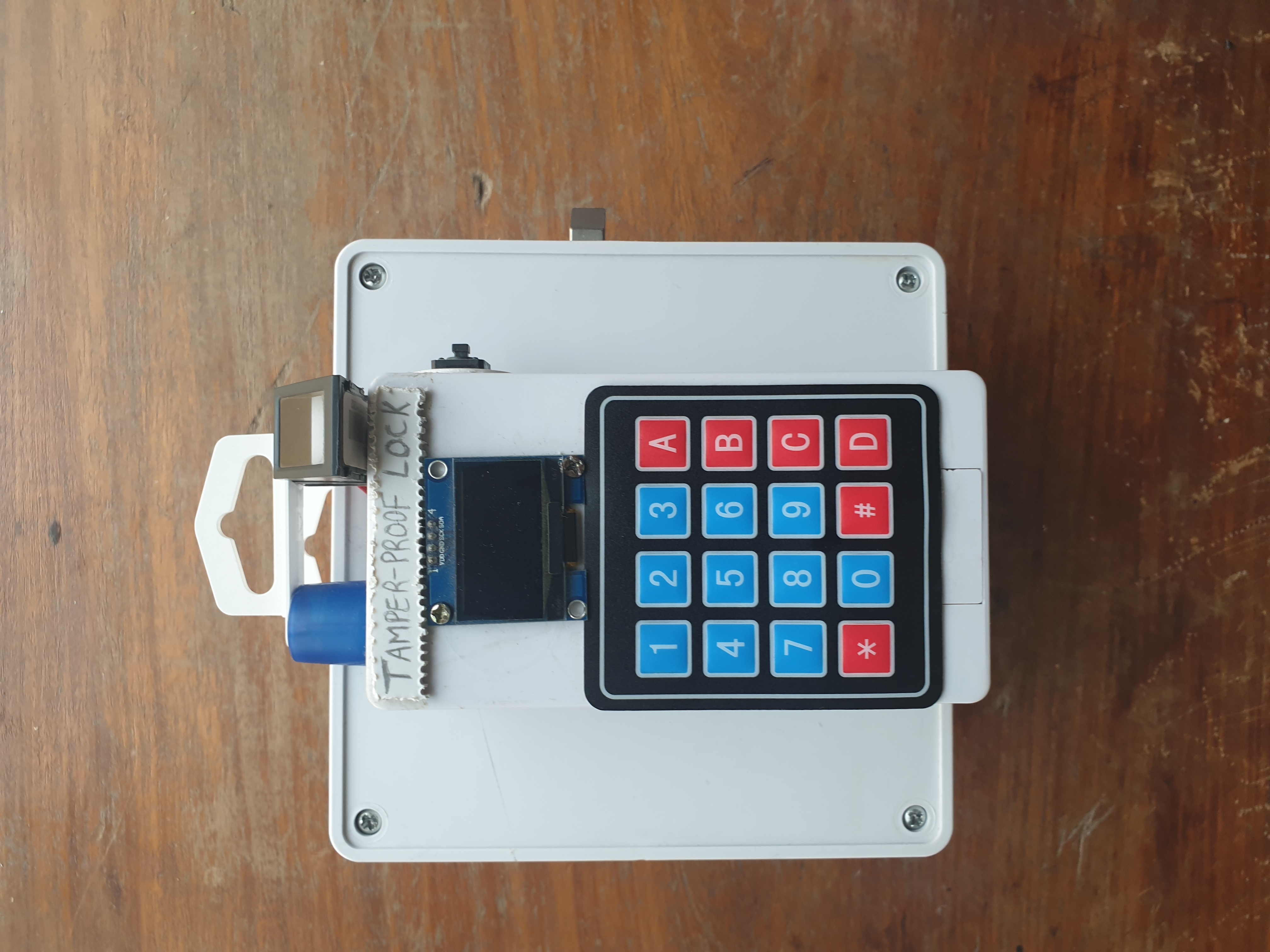
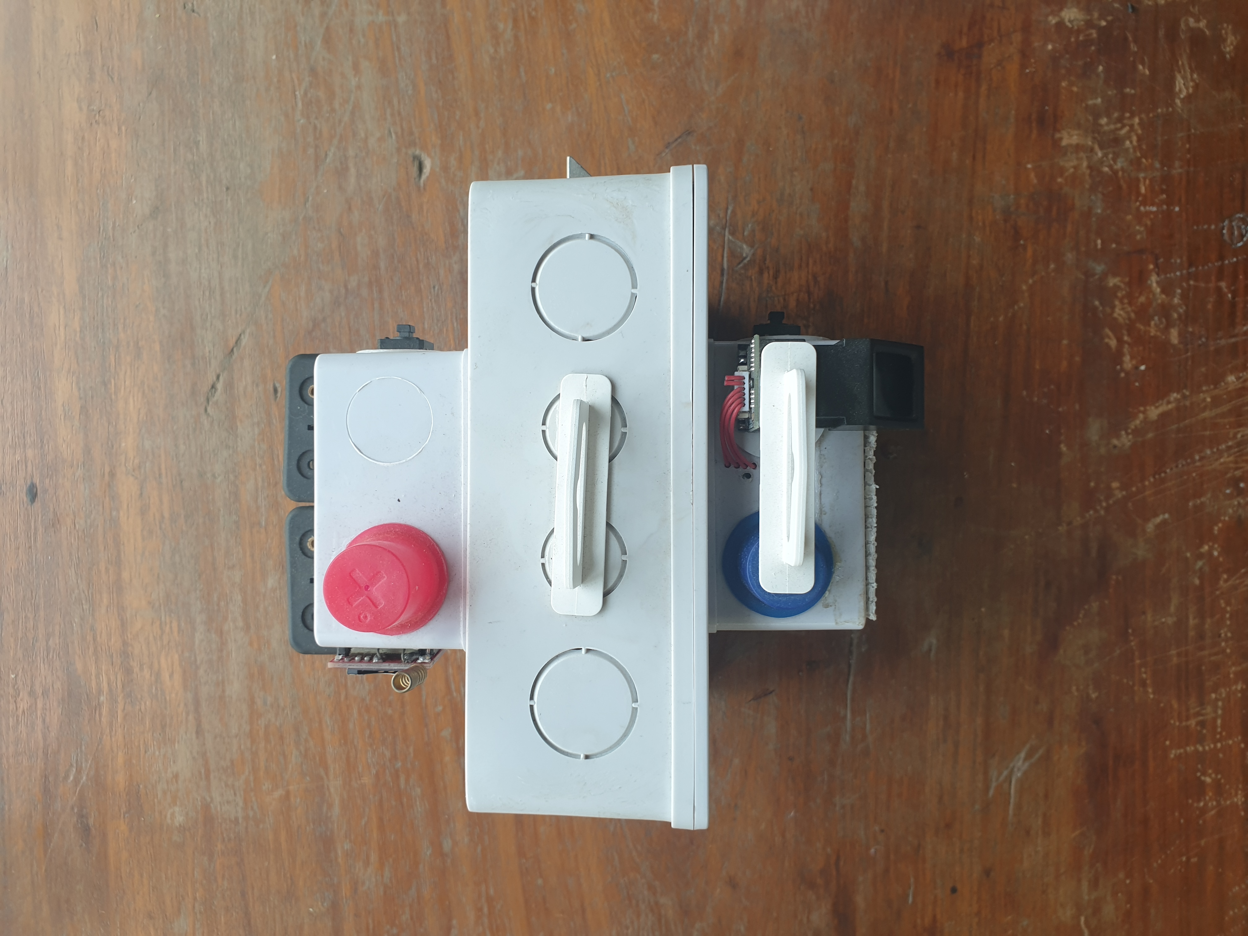
including fingerprint, keypad, mobile application, and tactile buttons. The system also features tamper
detection using an ultrasonic sensor, real-time responses to security breaches via SMS alerts, and a user
interface (keypad + OLED) to aid man-machine communication.
- Access control via:
- Fingerprint sensor
- Indoor and outdoor buttons
- Keypad
- Mobile app
-
Tamper detection via an ultrasonic sensor
-
Intruder alert via SMS
-
HMI (Keypad + OLED):
- To add/remove fingerprints
- To add a phone number
- To change the password
- Timekeeping occurrences of intruder and tamper detection using a Real-Time Clock.

- Keil uVision 5 for programming the STM32 microcontroller.
- MIT App Inventor for mobile application development.
- FreeRTOS (for concurrent execution of tasks).
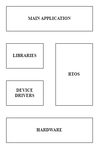
The software for the Smart Lock was designed using a layered architecture consisting of:
Device drivers(using CMSIS): UART, I2C, GPIO, DMA, SysTick, Timer, RCC.Libraries: These abstract the device drivers and provide an interface (function calls) for the main application
to control devices like the Fingerprint module, OLED, GSM module etc. without the need to know about their hardware configurations.Main application: A mix ofFreeRTOSand function calls from theLibrarieslayer.
The main application is divided into functions, FreeRTOS tasks and a software timer. All the tasks are given equal priority. The embedded application is split into the following:
Setuptask: This is the first task that is created and executed by the kernel. Before this task is created, clock configurations are made for the microcontroller and its peripherals. The setup task is responsible for initializing the components of the smart lock (e.g. keypad, fingerprint scanner, GSM module, OLED) as well as creating other tasks. It is executed just once. After performing its duties, it will be deleted from the memory utilized by the kernel.HMI and fingerprinttask: This task manages access control and security operations that are related to the HMI (keypad and OLED) and the fingerprint scanner. It handles the validation of passcodes and fingerprints. If three consecutive incorrect passcodes or fingerprints are detected, the following will occur:
a. Triggering of the buzzer and sending of SMS
b. Timekeeping of the intrusion event
c. Keypad and fingerprint scanner become temporarily disabledButtons and tamper detectiontask: This task handles inputs from the two tactile buttons and drives the solenoid lock accordingly. It also detects and responds to an event of device tampering. In response to a tampering event, an SMS alert will be sent, the buzzer will be activated, and the time of occurrence will be recorded.Bluetoothtask: This task is responsible for controlling the solenoid lock if the appropriate command is received via Bluetooth from a smartphone application. It also receives the passcode for the smart lock from the app. If the wrong passcode is sent 3 times, this task will trigger the buzzer, send an SMS alert to the authorized user, and temporarily disable communication with the mobile application. The Bluetooth task also sends records of intrusion and tampering attempts to the mobile application for security analysis.Software timer: The software timer is provided by the FreeRTOS kernel. It executes a piece of code (known as the software timer’s callback function) periodically. In this project, a software timer was created in order to handle timeouts. For example, if intrusion is detected by the HMI task, the buzzer will be triggered and the keypad and fingerprint scanner will be disabled for a specific time (8 seconds was used). The software timer’s callback function restores the system to its default state once this time expires i.e. buzzer will be turned off and the keypad and fingerprint module will be enabled in this case. The software timer was configured to trigger the callback every second.
The algorithm for the main application (functions, FreeRTOS tasks and software timer) is represented with flowcharts. All flowcharts can be found in the Flowcharts folder in this repo.
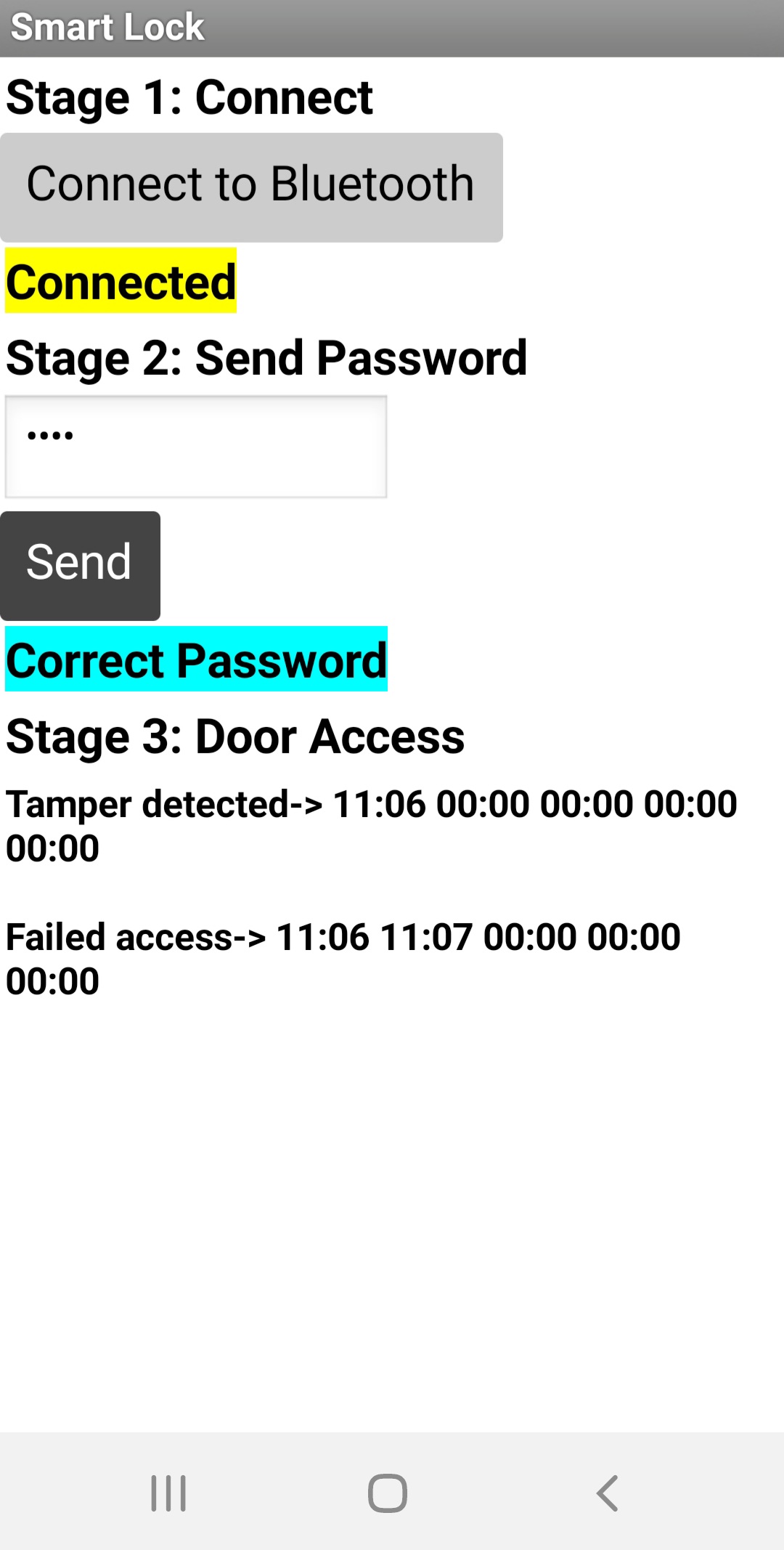
The app was developed using MIT App Inventor. The aia file can be found in
the App files folder of this repo. This file can be opened in MIT App Inventor
to view the source code. The APK file is also present in the same folder as the
aia file. The app communicates with the smart lock via Bluetooth.
| N | Component | STM32 |
|---|---|---|
| 1 | HC05 Bluetooth Module | USART3 (PB10, PB11) |
| 2 | Indoor Button | PA0 |
| 3 | Outdoor Button | PA1 |
| 4 | AT24C16 EEPROM | I2C1 (PB6, PB7) |
| 5 | DY50 Fingerprint Sensor | USART1 (PA9, PA10) |
| 6 | SIM800L GSM Module | USART2 Tx (PA2) |
| 7 | Ultrasonic Sensor | Trig pin: PA4, Echo pin: PA6 |
| 8 | 4x4 Keypad | PB0, PB1, PB5, PB8, PB9, PB12, PB13, PB14 |
| 9 | SH1106 OLED | I2C1 (PB6, PB7) |
| 10 | Solenoid Lock | PA3 |
| 11 | Buzzer | PA8 |
| 12 | DS3231 RTC | I2C1 (PB6, PB7) |
- The module should be powered with sufficient voltage (4.1 to 4.4v).
- It should also be powered with a supply that can source 2A or more.
- The wires connecting the power pins of the module to the supply should be as short as possible
to minimize resistance. This helps prevent unwanted resets (the resistance introduced
by longer wires could limit the current the module would draw).


This section lists the libraries adapted to meet the system's requirements.
- Adafruit Fingerprint Sensor Library: https://github.com/adafruit/Adafruit-Fingerprint-Sensor-Library
- STM32 Library for OLEDs: https://github.com/afiskon/stm32-ssd1306
- Power optimization (e.g., use of BLE instead of Bluetooth).
- Provision of an outlet for backup DC supply
- Provision of a port to enable AC power supply (alternate power source)
- Design and develop a mobile application with a better user interface