An alternative firmware for 433 MHz radio to wifi bridges, targetting these boards/microcontrollers:
| Board | Microcontroller | Passthrough | RCSwitch | Portisch | Notes |
|---|---|---|---|---|---|
| Sonoff Bridge R2 v1.0 (black box) | EFM8BB1 | Supported | Decode + Transmit (RfRaw 0xA5/0xA8) | Supported | Flashing works, see instructions below for Tasmota firmware upgrade |
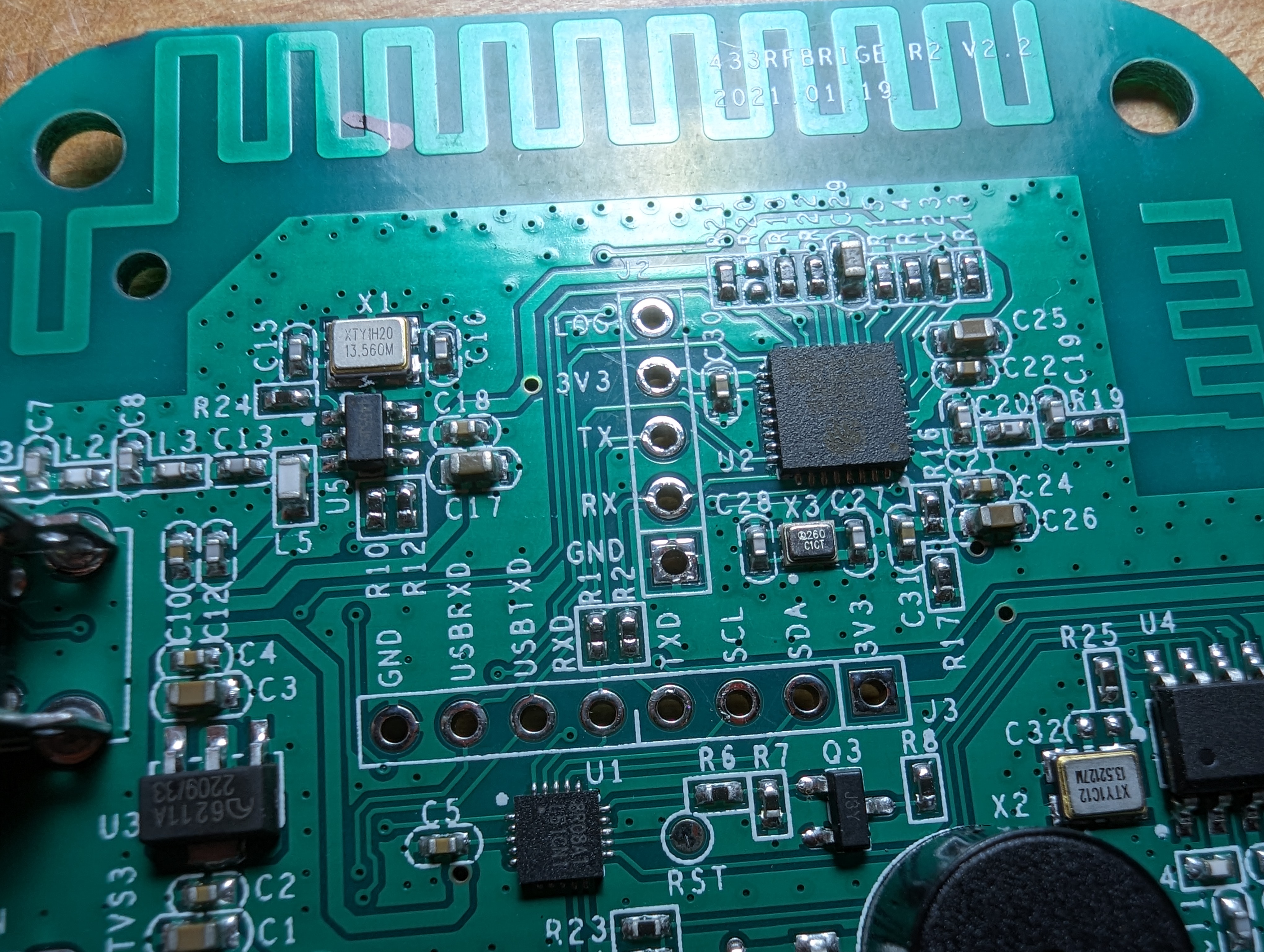
| Sonoff Bridge R2 v2.2 (white box) | OB38S003 | Supported | Decode + Transmit (RfRaw 0xA5/0xA8) | Supported | Requires reprogramming with official or open source flasher |
| EFM8BB1 Busy Bee Low Cost Kit Board | EFM8BB1 | Supported | Decode + Transmit (RfRaw 0xA5/0xA8) | Supported | Requires external receiver and/or transmitter |
These microcontrollers were originally intended for radio decoding but lacked support for code sniffing and additional protocols.
As a consequence many people just bypass the microcontroller with a hardware modification:
arendst/Tasmota#13283
Decoding may then be done directly on the ESP8265 wifi chip.
ESPHome/Tasmota/ESPurna are typically used for this purpose and integrated into Home Assistant.
The intent here is to avoid the need to perform hardware modification.
This can be accomplished by either one of two ways:
-
Mirroring the voltage levels between the radio data pins and the uart pins (used as gpio) already connected to ESP8265.
(i.e. passthrough firmware) -
Decoding/encoding radio packets on the microcontroller and sending formatted to ESP8265 over uart/serial
(ie., rcswitch or portisch firmware)
A benefit to keeping the microcontroller involved is that the radio LED and buzzer may still be controlled.
The downside is the effort required to develop firmware and flash by the end user.
The firmware radio decoding is inspired by the original
- RF-Bridge-EFM8BB1 (Portisch), and
- rc-switch projects.
THIS IS A WORK IN PROGRESS and requires multiple flashing steps.
Passthrough mode is the simplest, provided you are comfortable flashing ESPHome YAML or configuring Tasmota MQTT for your particular radio devices.
RCSwitch supports several standard protocols and is fast at decoding.
Portisch supports either standard protocol with sniffing of unknown codes or advanced decoding of multiple protocol timings.
If purchasing new devices I recommend using Zigbee or similar newer radio technologies.
These can be somewhat more expensive but are much quicker and simpler to pair devices and use immediately with Home Assistant:
https://www.home-assistant.io/integrations/zha/
If you do not wish to use the pre-build from releases, Install SDCC compiler for your platform:
https://sdcc.sourceforge.net/
On command line run make.
For now modify Makefile to select desired target (i.e. uncomment TARGET_MCU desired).
Built firmware is placed in 'build' directory.
See Flasher section below.
Reprogamming requires erasing the radio chip (e.g. OB38S003 microcontroller) because the stock firmware is protected.
The stock firmware cannot be recovered because it has not been read out.
Steps overview:
- Have an external flasher board prepared (see below).
- Connect the external flasher pins to the OB38S003 pins on the bridge (SCL<->SCL, SDA<->SDA, GND<->GND, leave 3.3V disconnected on microcontroller side until script instructs to cycle/apply power). See ESP8266 pinout and OBS38S003 pinout
- Download the firmware wanted and place in the same directory as flashscript.py
- Run FlashScript.py which will erase the OB38S003 and write the firmware you choose.
- Flash ESPhome/Tasmota to the RFbridge's internal ESP8265.
For OB38S003 microcontroller an official MSM9066 programmer or open source flasher (see below) can be used.
For EFM8BB1 microcontroller flashing can be done with Tasmota using the radio bridge's own internal ESP8265.
The module must be set as Sonoff Bridge (25) to allow flashing:
https://tasmota.github.io/docs/Modules/
Follow the instructions here to either flash original Portisch or a release from this repo:
https://tasmota.github.io/docs/devices/Sonoff-RF-Bridge-433/
An Arduino based flasher compatible with several boards such as ESP8265/ESP8266/ESP32 is available:
https://github.com/mightymos/OnbrightFlasher
Logic analyzer decodings of several flasher operations/programming cycles had been captured:
https://github.com/mightymos/msm9066_capture
The microcontroller radio chip can be flashed independently of the ESP8265 WIFI chip using the in circuit I2C interface on connector J3.
However the microcontroller manipulates serial lines which are shared with the ESP8265 flash interface.
Therefore (especially for passthrough firmware), some users were only successful by erasing the ESP8265 first, flashing ESPHome/Tasmota on to the ESP8265, and finally flashing the radio chip.
The following pins can be used in ESPHome / Tasmota:
-flash tasmota-sensors.bin to ESP on RFbridge
-configure module as e.g. Generic(0))
-save
now set pins to:
TX pin to GPIO1 (RFSend)
RX pin to GPIO3 (RFRecv)
WIFI LED pin to GPIO13 (LedLink)
See example YAML configs (https://github.com/mightymos/RF-Bridge-OB38S003/tree/main/example_esphome_yaml)
A successful attempt was made initially to compile "Portisch" with the open source SDCC compiler.
It remains challenging to fit all decoding protocols and sniffing features in code and ram spaces.
This effort allowed eventually porting to the R2 V2.2 Sonoff (white box).
https://github.com/mightymos/SonOfPortisch
There are at least three versions of rcswitch.
We attempt to use the simplest and most understandable for now (from sui77).
https://github.com/sui77/rc-switch
https://github.com/1technophile/rc-switch
https://github.com/arendst/Tasmota/tree/development/lib/lib_rf/rc-switch
The original Portisch for Sonoff (black box).
https://github.com/Portisch/RF-Bridge-EFM8BB1
We thank Vincent Defert for the use of modified makefiles and familiarity with 8051/8052 based microcontrollers:
https://github.com/area-8051/uni-STC