-
Notifications
You must be signed in to change notification settings - Fork 13.3k
New issue
Have a question about this project? Sign up for a free GitHub account to open an issue and contact its maintainers and the community.
By clicking “Sign up for GitHub”, you agree to our terms of service and privacy statement. We’ll occasionally send you account related emails.
Already on GitHub? Sign in to your account
Enabling UART2 for the NodeMCU? #482
Comments
Please check https://github.com/esp8266/Arduino#serial regarding Serial1 support. |
The idea was to be able to use two UARTS simultaneously (and the third one (TX1) for debug). BTW, how many UARTS does ESP8266 have? Are RDX2 and TDX2 just pin remaps for the same UART which is normally mapped on GPIO1/GPIO3, or are there two UARTS, and what Serial.swap() does is to swap between them? |
it has 2 UARTS only. but pins are swappable, that is why you see such markings. |
Thx for clarifying this. |
Hello friends I'm new to developing with esp8266, I'm trying to connect both an RFID reader rc522 and screen nextion 2.4 "in a NodeMCU 1.0, using arduino IDE v 1.6.11 to read an RFID tag and display the UID in Nextion 2.4 screen ". I managed to connect and work with each separately, but I can not make them work together. when the connections operate separately in NodeMCU v 1.0 are the following: Nextion 2.4 "||| MCU Node 1.0 5V-------------- 5V RC522 ||| MCU Node 1.0 3.3V------ 3.3V Both devices need to use the pin D7 (RXD2), I would like to use both at the same time, I read that I use UART but do not understand how to apply. any help is welcome |
also i try to work but no success .. i waiting |
It is explained above. Serial are mapped to GPIO1 and GPIO3, when you do "Serial.swap(); Serial.begin();" TXD2 and RXD2 are used, mapped to GPIO13 and GPIO15. But ESP8266 always have only one full Serial (Serial or Serial2) and one TX (Serial1). More info: https://github.com/esp8266/Arduino/blob/master/doc/reference.md#serial To solve the problem you must use SoftwareSerial Library or normal Serial in GPIO1 and GPIO3. |
Google led me here, correct link is now: https://github.com/esp8266/Arduino/blob/master/doc/reference.rst#serial |
Is it possible to use GPIO1 as TxD1? e.g. Serial.swap(); // Swap to Alternate pins -> EQG on "Serial" (RxD-nn, TxD-nn) delay(1000); // Wait for a second Serial.println("Test 13, 15"); // Serial string appears on line attached to 13, 15 Serial1.begin(9600, SERIAL_8N1, SERIAL_FULL, 1); // Set "Serial1" as debug, swap to GPIO1 (i.e. output to USB connected to download port) |
I tried. Did not work. |
Did you wire the Tx to the Rx on the serial device connected to pins GPIO 15. Output to Input. |
Probably a misunderstanding. The swap to pin13 and 15 worked. But I didn't get a swap to GPIO1 to work, |
Question: Does the Swap function cause a problem reprogramming the device. When swapped the normal IDE pins are no longer connected? |
pull this pin to gnd (with resistor) or modify library miguelbalboa/rfid#599 (comment) |
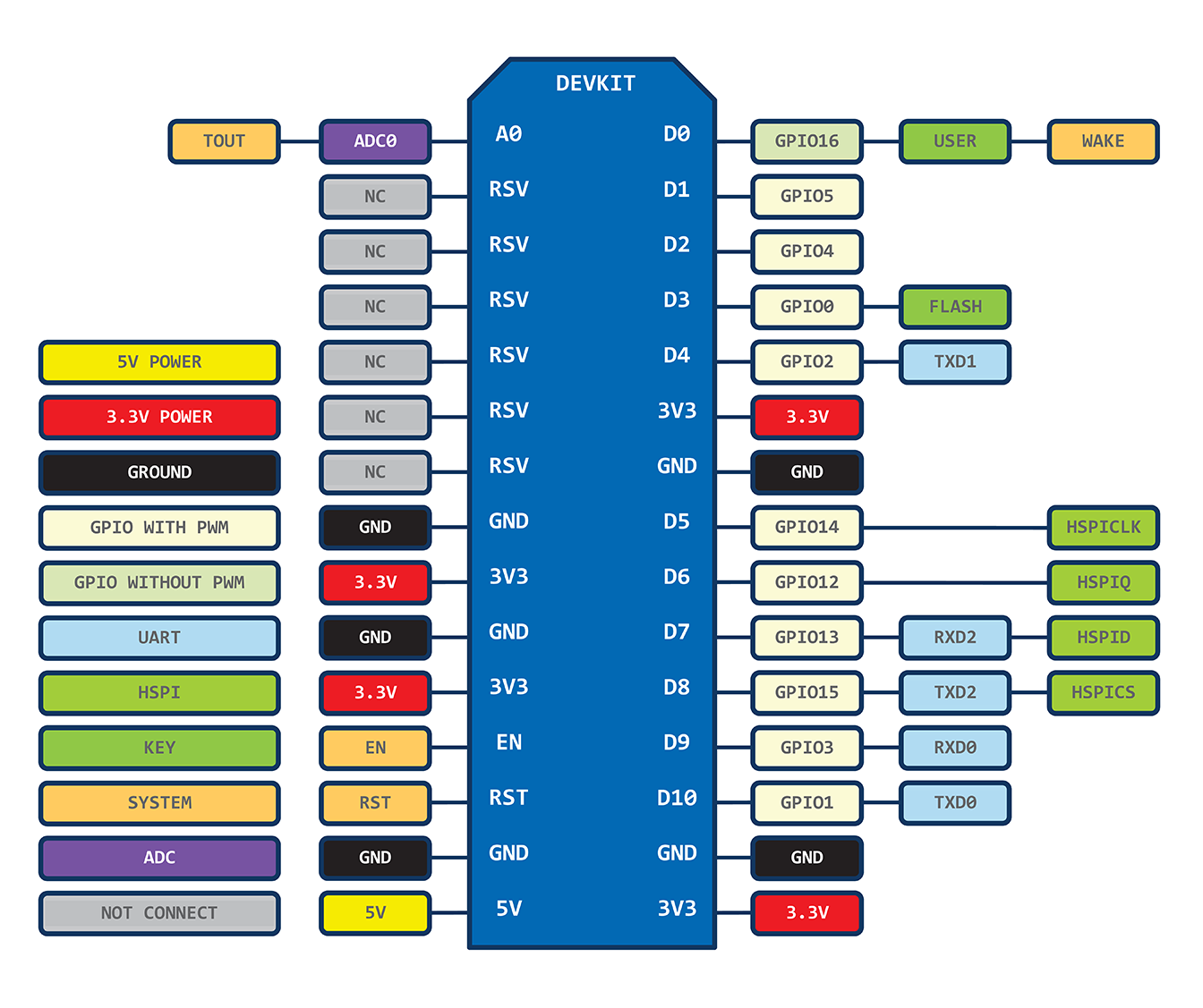
The NodeMCU V1.0 (the new one) is showing a RDX2 and TDX2 on the pins D7 (GPIO13) and D8 (GPIO15). Any chance to have a Serial2 for them?
Best regards, you are doing a great work!
https://raw.githubusercontent.com/nodemcu/nodemcu-devkit/master/Documents/NODEMCU-DEVKIT-INSTRUCTION-EN.png
The text was updated successfully, but these errors were encountered: